| Package import | "zappem.net/pub/io/glase" |
|---|---|
| Documentation | https://pkg.go.dev/zappem.net/pub/io/glase |
| Sources | https://github.com/tinkerator/glase |
There is no official support for Linux for this LASER, but I wanted to use it with some scriptable projects so I’ve developed this package and a cli tool to bridge that gap in a way that meets my needs. See the References section below for a gui alternative.
Before using this tool, and the Omni 1 in general, do yourself a favor and watch this highly accessible video. Or this shorter, drier, video. All tools are potentially dangerous. A LASER like this definitely is.
Be sure to wear 355nm UV protecting LASER eye protection whenever the LASER is powered on.
Build and kick the tires (no LASER activity from this first example):
$ git clone https://github.com/tinkerator/glase.git
$ cd glase
$ go build examples/glase.go
$ ./glase --info
To get started, assuming you have the 150mm lens installed in your
device (this was the default when I received mine), you also need to
copy the jcz150.cor file to your working directory and rename it
local.fixup.cor. (Creating a new file instead is covered in the
Recalibrating section below.)
mfg="BJJCZ" product="USBLMCV4" ..., so I won’t be
surprised if a different device misbehaves.--serial=<xxx> on the command line to operate on a
specific one.libusb-1.0 not being found, try
one of the following and then the go build examples/glase.go
command again:
sudo apt install libusb-1.0-0-dev pkg-configsudo dnf install libusb1-devel pkgconfig-pkg-configbad access [code -3] error.
sudo nano
/etc/udev/rules.d/99-omni1.rules
, with this content:# This rule was added for the ComMarker Omni 1 5W UV LASER device.
SUBSYSTEM=="usb", ENV{DEVTYPE}=="usb_device", ATTRS{idVendor}=="9588", ATTRS{idProduct}=="9899", MODE="0666"
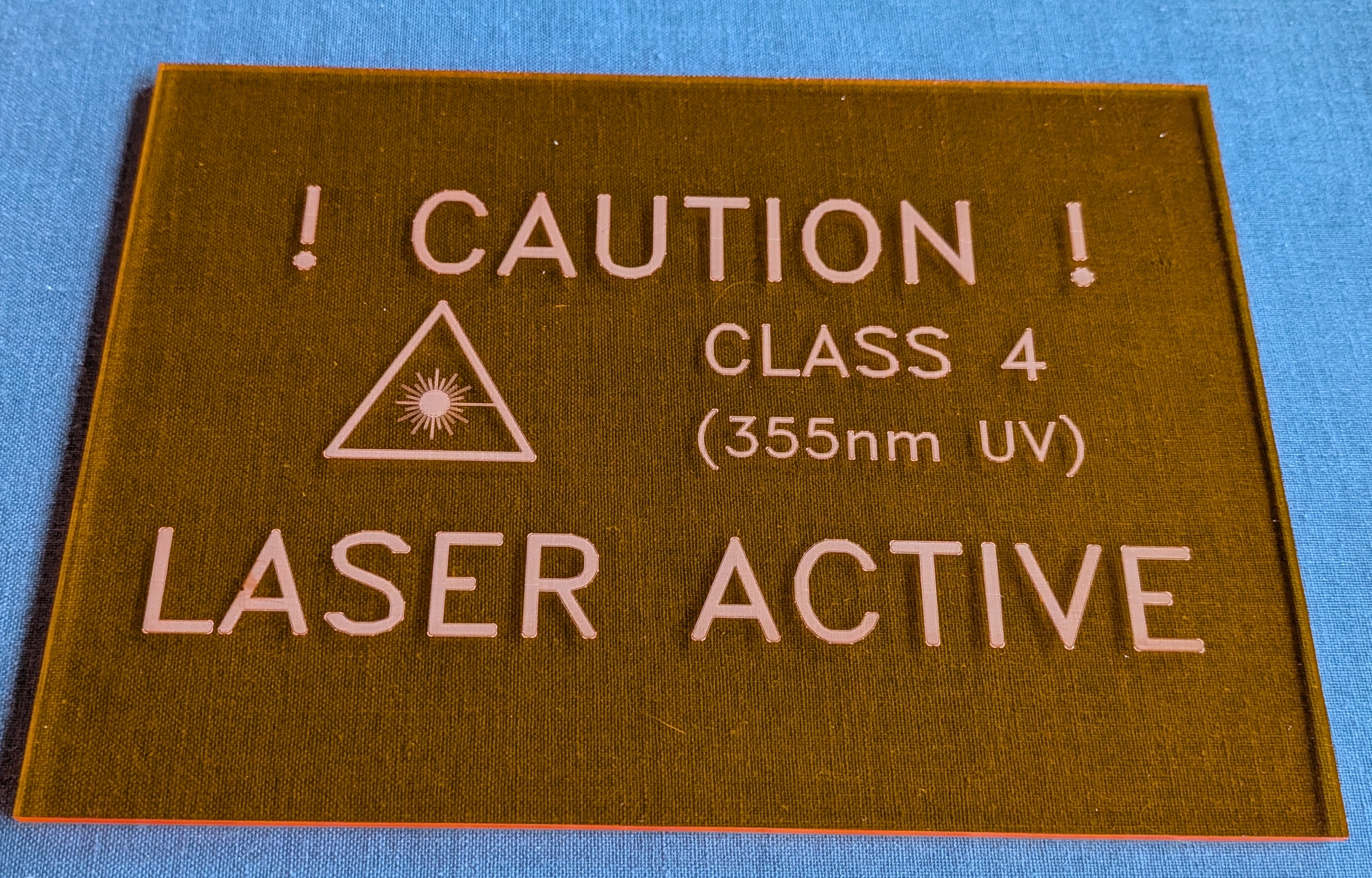
sudo udevadm control --reload-rules and also sudo udevadm trigger.The examples/glase.go tool can be used to make a LASER caution sign. I used
the following commands:
$ go build examples/glase.go
$ ./glase --burn-speed 1000 --hatch .2 --laser --size 30 --x -40 --burn
$ ./glase --burn-speed 1000 --hatch .2 --banner "CLASS 4" --size 20 --x 30 --y 10 --burn
$ ./glase --burn-speed 1000 --hatch .2 --banner "(355nm UV)" --size 15 --x 30 --y -5 --burn
$ ./glase --burn-speed 1000 --hatch .2 --banner "! CAUTION !" --size 35 --y 30 --burn
$ ./glase --burn-speed 1000 --hatch .2 --banner "LASER ACTIVE" --size 35 --y -30 --burn
On an acrylic sheet using my system, the result looks like this:
The LASER is shipped with a copy of EZCad2 Windows software on a USB
stick. My Omni 1 arrived with the 150mm lens mounted on the LASER. The
USB stick had a file jcz150.cor on it that was the distortion
correction file for my LASER. It seemed to mostly work fine (--cor
jcz150.cor). But I found it generated a non-square coordinate pattern
at the left edge of its 15cm range. After teaching the glase package
to consume this file format and upload it to the LASER, I followed the
following strategy to generate a new local.fixup.cor file for my
specific LASER.
This is the procedure I followed:
I placed a transparency sheet (the type you can use with a LASER printer) flat on the work surface of the machine and adjusted its z-height to match what the factory said was the focal point of the LASER.
I then burned a barrel distorted calibration grid with default parameters over this sheet (without any correction data applied):
$ ./glase --cor "" --burn --calibrate
The grid spacing generated by the --calibrate flag is 1000 galvo
units of distance (with 64 squares, this is a total galvo unit range
of 64000). For the official height of focus of my LASER this 1000 unit
distance burned marks on the transparency sheet close to 1/10th of an
inch (or 2.5mm). So, I derived a correction file that forces exactly
this normalization. That is, 1000 galvo units is, by definition,
2.5mm.
Next, by examining the outer 4 corners of the grid, its center point
and the central point of each of the 4 sides you can capture
information needed to make the grid rectangular. That is details about
these 9 points can be used to generate a new .cor file. To do this,
create a local.fixup file with information about how much each of
these 9 points deviated from its ideal point. For example, I took the
center point (0,0) in galvo units to be the true mm center of the
LASER’s range. Further, the outer edge centers appeared to be aligned
well with this center point to generate a convenient perpendicular
cross. From the center, however, they just weren’t exactly 8cm in
length. Finally, I looked at how the outer 4 corners of the grid
deviated from the (+/-8cm,+/-8cm) positions I wanted. I corrected for
all this with these 9 lines in the .fixup file (if you repeat this
exercise with your LASER, you may get different numbers):
# Assumed origin (adjusted later with X and Y entries).
0 0 0 0

-32 0 -2 0
32 0 2.5 0
0 -32 0 -2.5
0 32 0 3.5

-32 -32 2 -4
-32 32 1.5 5
32 32 0 5.5
32 -32 -2 -4
Each line of this file is of the following form: xGrid/1000,
yGrid/1000, mmXWrong, mmYWrong. That is the mm*Wrong values
capture how wrong the rendered crossing point is in mm. So, if a
rendered point is a little to the right, its mmXWrong value is
positive by that many millimeters. To be very clear about orientation,
in the conventions glase uses, the smallest (most negative) Y values
are closest to the front of the machine - the edge that features the
red emergency stop button. Left (negative X) and right (positive X)
are as viewed from this front of the machine.
The first line of this file says no correction is needed for the origin point (0mm,0mm). The next two lines say no Y correction is needed, but the rendered (-8cm,8cm) X-axis line, without correction, is observed to be 4.5mm (or 2.5-(-2) mm) too long. Similarly, the rendered (-8cm,8cm) Y axis line is 6mm too long. It took a few attempts to get the remaining 4 point corrections to generate a correct 2.5mm grid. Indeed, for my LASER, the bottom corner points seemed to resist rendering as (+/-8cm,-8cm) points. This is, I presume, the reason the ComMarker writeup asserts the LASER only has a 15cm range.
To create a custom local.fixup.cor file from this data, do this:
$ ./glase --cor local.fixup --regen --sim
local.fixup.cor file’s content starts at
byte offset 36. The bytes before that are not important to the
glase package, and other than the JCZ_COR_2_1 magic, are mostly
filled with nonsense bytes. I have no idea if the generated file
will work with the EZCad2 software. I don’t intend to bother trying
that.The ./glase tool can operate directly with an ASCII .fixup file
(omit the --regen argument), or a .cor file. It defaults to
looking for a local.fixup.cor file in the working directory. So, if
you want to use the jcz150.cor file you received with your machine,
supply that info explcitly on the command line as --cor jcz150.cor,
or make a local copy of that file with the local.fixup.cor name.
Using a ruler we can compare the grid spacing and confirm that the grid is calibrated. However, the laser itself has an intrinsic X-Y plane that may not be fully orthonormal, and may not quite align its origin with the base platform of the Omni 1.
I 3D printed a frame to hold my work under the laser and found that there was a discrepancy when mounting a board on that frame front-upwards vs front-downwards. The difference was less than 0.5 mm, but presented a problem when scribing out traces for through-hole pins.
To address this I developed a refinement strategy using a translucent
plastic sheet. Mounting the sheet upward-facing and scribing some 2mm
x 2mm squares at symmetric points over the surface of the board, and
then flipping the board over the Y-axis of the frame and then scribing
the same locations on the reverse side, I found some O(mm) deviations
in the locations of the squares. If the coordinate system of the laser
was aligned with that of the frame, these squares should align through
the translucent board. Since they did not, I averaged the (x,y) of the
“reflected” underside square of every front-side square, and in the
imperfect LASER XY coordinates determined a set of points on the true
Y-axis of the mount. Similarly, I did the same operation to find true
frame X-axis points. These points were added to the end of the
.fixup file as follows:
# Assumed origin (adjusted later with X and Y entries).
0 0 0 0

-32 0 -2 0
32 0 2.5 0
0 -32 0 -2.5
0 32 0 3.5

-32 -32 2 -4
-32 32 1.5 5
32 32 0 5.5
32 -32 -2 -4

# Y axis fixup
Y     0.5       70.025
Y     0.5         69.8
Y     0.1        -69.9
Y   0.125      -70.125
Y    0.45        50.15
Y    0.15        49.75
Y     0.1        -49.8
Y  -0.075      -50.125

# X axis fixup
X   -19.8        -0.15
X    20.1       -0.325
X   -20.2       -0.125
X   19.85        -0.25
X  -39.85        -0.15
X  40.075       -0.425
X  -40.15         -0.1
X  39.875         -0.4
By observing the crossing coordinate of these two lines, I was able to
determine the true (frame) origin (X=0,Y=0) point. Preserving the
“distance from that point” of the measured axis points, I could infer
the “true” XY coordinate directions of the true axes for the frame. I
modified the glase .fixup parsing code to derive an Affine
transformation from these true axes points, and use that to enhance
the calibration data to align the LASER XY coordinates with those of
my mounting frame. Effectively aligning the laser coordinates with
those of my 3D printer.
The glase package is distributed with the same BSD 3-clause
license as that used by
golang itself.
This is a hobby project, so I can’t guarantee a fix, but do use the
github glase bug
tracker.