| Sources | https://github.com/tinkerator/cncprober |
|---|
The cncprober is a CNC
prep tool for a Snapmaker A350. Its purpose is to center a 200W CNC
head on a PCB workpiece (a conductive metal board). It may also be
usable for other conductive meterials, but be conscious about what
materials the A350 + 200W CNC module can
cut.
NOTE: Since it will physically drive a Snapmaker A350 CNC machine, and this setup does nothing to regulate voltage output from that device, there is a real possibility it will cause damage.
CAUTION: the probing works empirically for me, but the exact way in which the floating grounds between the RPi and the Snapmaker 200W CNC module interact is not clear. I’m exploring some isolation circuitry to protect the RPi but, for now, the method described here is what I’ve been using…
NOTE: As per the LICENSE, you will be using the tool without a safety net and “IN NO EVENT SHALL THE COPYRIGHT OWNER OR CONTRIBUTORS BE LIABLE FOR ANY DIRECT, INDIRECT, INCIDENTAL, SPECIAL, EXEMPLARY, OR CONSEQUENTIAL DAMAGES…”.
This tool requires some RPi hardware setup to use. I’ve used a RPi Zero W2 device that I also use to host a camera, but you can likely use any RPi or adapt things to work with some other Linux based microcontroller.
To get started, you can run a (long) wire directly from the RPi to the CNC bit (CAUTION: don’t let the CNC turn the bit with that connection in place!). See below (Advanced implementation) for the way I’ve actually implemented the CNC bit HW connectivity that appears to avoid the need to disconnect the wire when drilling something…
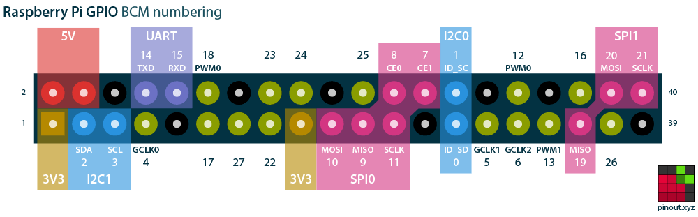
The two GPIOs used for this tool default to these values, but you can use the command line flags to override these values:
| GPIO | Flag to override | Connected to | Purpose |
|---|---|---|---|
| 22 | --probe |
The CNC bit. | Read the voltage of the CNC bit. |
| 23 | --signal |
Target board. | Read the voltage of the board. |
NOTE: the GPIO voltage settings fluctuate through the probing process, so if some voltage sticks, the tool should not get confused, but error out gracefully.
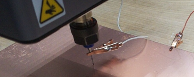
To connect things, I used two “flexible” wires and soldered them to two halves of a female to female RPi connector wire. That is, I cut a single one of these wires in half, and paired a half with each of the flexible wires. I soldered the cut end of each half to its paired flexible wire. In this way, I could connect the two flexible wires to my RPi. The other ends of the two flexible wires are connected to aligator clips.
You will also need one “long enough” extra wire to briefly touch connect the CNC bit directly to the board, and unpause the program. This wire will not be connected for more than a second, but it helps the program confirm that connectivity checking works at time of program start - before the program initiates motor control of the CNC.
Next up is the SW: the cncprober tool, which should be compiled for
and run on a RPi to exploit this conductive path and enable RPi GPIO
touch probing (aka touch-off, Z-probing, supporting a touch
plate. In more professional contexts, this functionality is a regular
part of CNC bit tool setting.)
Build and install tool (replace your-rpi with, well, your RPi):
$ git clone https://github.com/tinkerator/cncprober.git
$ cd cncprober
$ GOARCH=arm64 go build cncprober.go
$ scp cncprober pi@"your-rpi":
$ ssh pi@"your-rpi":
The machine CNC has to be homed before the program can run. To do
this, you can home it from the touch panel, or from the command line
with the examples/snappy
program. In fact, to be able to use the cncprober program, you will
need the ~/.snappy.conf file from that last package setup, so
we’ll assume you have completed the “Running the example” demo from
the snappy package.
$ ./snappy --home
If you have the enclosure for your Snapmaker A350, you can also start the enclosure exhaust fan with:
$ ./snappy --fan 100
This ./snappy tool can also be compiled for a RPi (see how we built
the cncprober program). So, all of the commands on in this README
could be performed directly via the RPi.
With the machine homed, and with a copy of your ~/.snappy.conf
file on your RPi:
$ scp ~/.snappy.conf pi@"your-rpi":
you are ready to try the program. Jog (aka nudge) the CNC from its Home position to somewhere over your target board. You can adapt something like this relative movement:
$ ./snappy --nudge-x 170 --nudge-y -190
But, you may have to nudge differently to fine-tune the position to be somewhere directly over your target board. Be sure to have wired up your RPi to the target board and the CNC bit as described above before trying the next thing (on your RPi):
$ ./cncprober --lower
This will lower the height (Z-axis coordinate) of the CNC Toolhead,
until the RPi senses the bit is touching the target metal. However,
before attempting a move, the ./cncprober will wait to see a
short-lived contact between the CNC bit and the board:
2026/07/26 14:35:36.798757 Please wait while we initialize GPIOs and the A350 connection
2026/07/26 14:35:40.156260 Connected to tool=15 "levelTwoCNCToolheadForSM2"
2026/07/26 14:35:41.157291
2026/07/26 14:35:41.157429 Be sure GPIO<22> wired to the CNC bit, and GPIO<23> to the target board.
2026/07/26 14:35:41.157495
2026/07/26 14:35:41.951451 probe GPIO22 is changing=true
2026/07/26 14:35:41.951573 Begin by touching a loose wire to board and CNC bit...
changing=true), you
likely have a wiring problem. Double check that the GPIOs are
connected as described above to the target board and the CNC bit.It is time to use the extra wire. You should press one end to the board, and one end to the CNC bit. This confirms that the GPIO circuit will detect when the CNC bit (probe) does touch the board directly. When you do that, the probing will start as follows:
2026/07/26 14:35:42.101739 ...detected! Remove this loose wire and stand back we're about to move!
With the touch completed, remove this extra wire and stand back to
admire the program do its work:
2026/07/26 14:43:56.711982 Starting from (151.00,137.00,143.00) offset=(0.00,0.00,0.00)
2026/07/26 14:44:37.397571 Failed to find surface. Try --lower again?: no probe connection above (151.000000,137.000000,0.000000)
This is the expected output on your first invocation. The program
doesn’t want to destroy the CNC bit, so it is cautious about lowering
too far. That is, by default, cncprober is only willing to lower
12mm without sensing a conductive loop between the two GPIOs.
You can keep re-running the program and the CNC head will lower 12mm
more, unless it senses the conductive target surface first. If your
patience is running thin, you can supply the --travel=120 argument
to venture 10 times that distance instead before giving up. Be
warned, if you are not over the metal surface, this will likely
drive the CNC bit into the base board, yielding some destruction. I
suggest guessing “half the distance” and iterating a bit. If you
notice that the downward motion is revealing that the head is not in
fact over the board, snappy command to nudge
the head appropriately in the X and Y directions until the head is
over the board, and then resume the probing.
After enough iterations, the CNC bit will touch the board and the program will set the work origin to the discovered (X,Y,Z) coordinate of that point of contact.
Here, I use the --danger argument to skip needing to manually touch
the points, and ask for --travel=30 mm as an override of the default
12mm. It exits after 28.5mm of travel having found the surface:
$ ./cncprober --lower --danger --travel=30
2026/07/26 14:47:49.484345 Please wait while we initialize GPIOs and the A350 connection
2026/07/26 14:47:49.733387 Connected to tool=15 "levelTwoCNCToolheadForSM2"
2026/07/26 14:47:50.735145
2026/07/26 14:47:50.735488 Be sure GPIO<22> wired to the CNC bit, and GPIO<23> to the target board.
2026/07/26 14:47:50.735644
2026/07/26 14:47:54.636463 probe GPIO22 is changing=true
2026/07/26 14:47:54.636546 Danger mode enabled: assuming you have wired things up correctly...
2026/07/26 14:47:54.636567 Starting from (151.00,137.00,131.00) offset=(0.00,0.00,0.00)
2026/07/26 14:49:54.497949 Setting work origin to probed surface point (151.00,137.00,102.50)
You can validate that this is the surface with a command that does not move the CNC module, just validates that the probe and the board are connected:
$ ./cncprober --validate
2026/07/26 14:50:06.846517 Please wait while we initialize GPIOs and the A350 connection
2026/07/26 14:50:08.299510 Connected to tool=15 "levelTwoCNCToolheadForSM2"
2026/07/26 14:50:09.300644
2026/07/26 14:50:09.300721 Be sure GPIO<22> wired to the CNC bit, and GPIO<23> to the target board.
2026/07/26 14:50:09.300778
2026/07/26 14:50:11.999456 probe GPIO22 is changing=true
2026/07/26 14:50:11.999596 Begin by touching a loose wire to board and CNC bit...
2026/07/26 14:50:12.150358 ...detected! Remove this loose wire and stand back we're about to move!
2026/07/26 14:50:12.150878 Sleeping for 10 seconds to allow you to back away...
2026/07/26 14:50:22.301974 Current location is (0.00,0.00,0.00) offset=(-151.00,-137.00,-102.50)
2026/07/26 14:50:22.302193 Connected = true
Knowing some point on the surface is good, but likely not sufficient. Indeed, what would be better would be to find some reference point on the surface - the (rough) center for example. This can be achieved (with the underlying assumption that the surface is rectangular) with a different command:
$ ./cncprober --center
This particular command requires that the --lower command has
completed and left the CNC bit touching the surface. It will error
out, if there is no detected contact, and will further error out, if
raising the head slightly does not break this contact. You can
compound these operations on first use, with the combined command
./cncprober --lower --center, in which case, the former will be
sequenced before the latter:
$ ./cncprober --lower --center
2026/07/26 14:57:14.033066 Please wait while we initialize GPIOs and the A350 connection
2026/07/26 14:57:15.214114 Connected to tool=15 "levelTwoCNCToolheadForSM2"
2026/07/26 14:57:16.215332
2026/07/26 14:57:16.215440 Be sure GPIO<22> wired to the CNC bit, and GPIO<23> to the target board.
2026/07/26 14:57:16.215562
2026/07/26 14:57:19.186337 probe GPIO22 is changing=true
2026/07/26 14:57:19.186409 Begin by touching a loose wire to board and CNC bit...
2026/07/26 14:57:19.637579 ...detected! Remove this loose wire and stand back we're about to move!
2026/07/26 14:57:19.637695 Sleeping for 10 seconds to allow you to back away...
2026/07/26 14:57:29.812025 Starting from (0.00,0.00,0.00) offset=(-151.00,-137.00,-102.50)
2026/07/26 14:57:30.138867 Setting work origin to probed surface point (0.00,0.00,0.00)
2026/07/26 14:57:30.280814 current location: (0.00,0.00,0.00) offset=(-151.00,-137.00,-102.50)
2026/07/26 14:57:30.712466 Centering X on board...
2026/07/26 15:00:02.086250 Centering Y on board...
2026/07/26 15:02:34.908090 Deduced origin {18.703 1.203} (shifting work origin to there)
2026/07/26 15:02:35.217867 Starting from (9.35,1.20,1.00) offset=(-151.00,-137.00,-102.50)
2026/07/26 15:02:38.926599 Setting work origin to probed surface point (9.35,1.20,-0.10)
The --center operation jumps around the board trying to determine
the X edge locations at the current Y coordinate. Having found these
two extremes, it centers the X value (temporarily defining a new work
origin) and then proceeds to do the same with the Y
coordinate. Ultimately, it determines the center of the board with
this discovered X and Y coordinate.
Try to ensure that the location of the crocodile clip on the board does not align with an up<->down and left<->right cross over the surface of the board, as this will be probed by this process.
If the surface height differs by more than 0.5mm, the tool will
assume the lower parts are beyond the edge of the surface. (You can
override this default with the command line flag --edge <deep>
mm.) This default value is useful since I’ve been working with 0.8mm
thick PCBs.
If your rectangular target board is placed at an angle to the natural X-Y plane of the A350, then the tool may not find the true center.
If your target surface is not rectangular, then that center may not be recognizable as one.
If your surface has concave properties, you are likely to get very strange results.
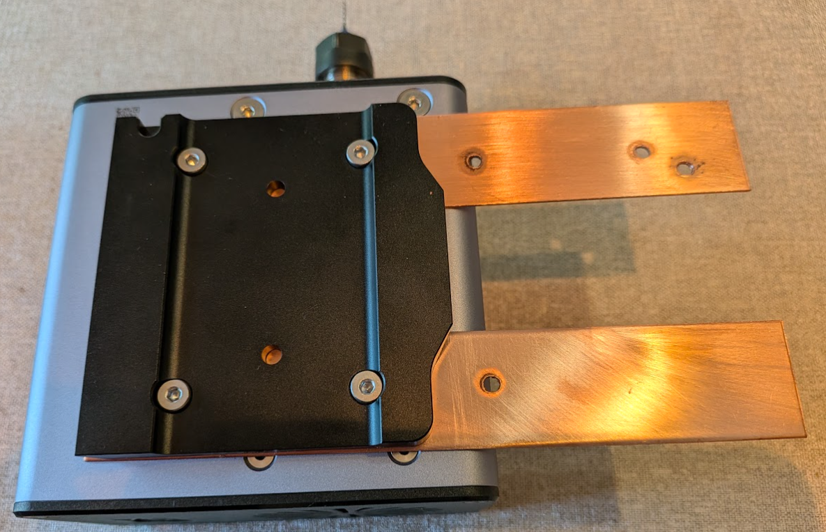
The CNC bit on the Snapmaker A350 CNC head isn’t wired up in any way that the Snapmaker CNC controller exports, and Snapmaker didn’t implement a touch plate. However, this device appears to have a conductive path from the CNC bit to the bolt holes that are used to mount the CNC head to the galvenized (non-conducting finish) quick swap kit. When I realized this, I took a pair of copper strips and using the 3.175mm Nano Blue Coat End Mill CNC Router Bit drilled two 3.3mm holes in each of them, 40mm apart:

I then used a Pittsburgh Carbon Steel Metric Tap and Die Set M4-0.7 thread tapping bit to turn these 3.3mm holes in the copper into M4 threaded holes. This is the bolt type used to mount the quick-swap enabling mounting plate to the CNC head.
I reconnected the quick-switch plate but with these two copper strips sandwiched between the plate and the CNC router head. The M4 bolts electrically connect to the threaded copper strips’ threads and can conduct electricity to those copper strips and, in this way, I was able to expose an electrical connection to the CNC bit on a non-rotating surface.
Investigate if the older 50W CNC module behaves the same way (I’ve not tried it).
Investigate the electrical stability of this connection. I want to confirm that the voltage range is safe for RPi to connect to. I intend to develop some circuitry to protect my RPi in case it isn’t safe.
With an oscilloscope, when the board and CNC bit are not connected to RPi input GPIOs, there is a visible ~500mV fluctuating voltage difference between the board and CNC bit. This difference disappears when the two metal surfaces come into contact. The fluctuation appears to have a period matching the 60Hz AC voltage where I live.
The nature of this voltage difference grows dramatically when the GPIO input pins are connected one to the CNC bit and one to the board. I suspect this is some sort of floating ground combined with RPi pullup resistors effect. This amplitude is enough to observe with the GPIO polling code and as such allows this probing method to work. That being said, even though it seems highly reproducible, I’m not fully clear what is going on.
What I do observe is that grounding the RPi to an external ground diminishes the effect considerably.
The cncprober tool is distributed with the same BSD 3-clause
license as that used by golang
itself.
This is a hobby project. No support should be expected. However, if
you want to suggest a feature, or if you find a bug, please use the
github cncprober bug
tracker to discuss
it.